|
|
 |
Customized Multi Axis Motorized Piezo Stage
Customized Multi Axis Motorized Piezo Stage, Contact us for specific models
|
|
6-8 weeks |
Request for quote |
|
|
|
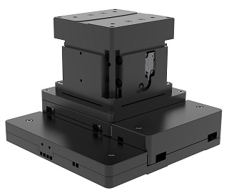 |
ST-XY3-5050+ST-VS-0812
Multi Axis Motorized Piezo Stages, X,Y Stage Stroke +/-25mm, Z Stage Stroke +/-6mm, Driver Piezoelectric Motor, Maximum Load Capacity 2KG, Maximum Speed 30mm/s, X,Y Stage Minimum Step Size 50nm, X,Y Stage Repeatability +/-200nm, Z Stage Minimum Step Size 50nm, Z Stage Repeatability+/-200nm, Material Aluminum Alloy
|
|
6-8 weeks |
Request for quote |
|
|
|
|
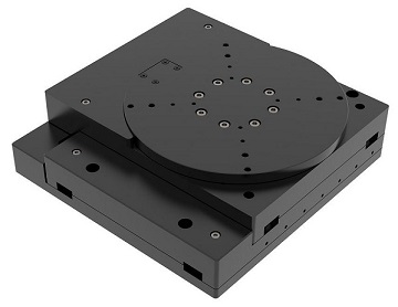
ST-XY3-5050+ST-VS-0812
Multi Axis Motorized Piezo Stages, X,Y Stage Strok +/-25mm, R Stage Stroke +/-6°, Driver Piezoelectric Motor, Maximum Load Capacity 10KG, Maximum Speed 30mm/s, X,Y Stage Minimum Step Size 100nm, X,Y Stage Repeatability +/-200nm, R Stage Minimum Step Size 0.0005°, R Stage Repeatability +/-0.0005°, Material Aluminum Alloy
|
|
6-8 weeks |
Request for quote |
|
|
|
 |
XYR-202020
Multi Axis Motorized Piezo Stages, X,Y Stage Stroke 20mm, R Stage Stroke 20°, Driver Piezoelectric Motor, Maximum Speed 50 mm/s, Minimum Step Size 200nm, X,Y Stage Repeatability +/-300nm, R Stage Minimum Step Size +/-0.001°, Material Aluminum Alloy
|
|
6-8 weeks |
Request for quote |
|
|
|
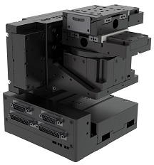 |
Six-axis Motorized Piezo Stage
Multi Axis Motorized Piezo Stages, X Stage Stroke +/-12.5mm, X Stage Minimum Step Size 100nm, X Stage Repeatability +/-300nm, Y Stage Stroke +/-12.5mm, Y Stage Minimum Step Size 100nm, Y Stage Repeatability +/-300nm, Z Stage Stroke +/-10 mm, Z Stage Minimum Step Size 100nm, Z Stage Repeatability +/-300nm, R Stage Stroke +/-5°, R Stage Minimum Step Size 0.0002°, R Stage Repeatability+/-0.0004°, G Stage Stroke+/-5°, G Stage Minimum Step Size 0.0002°, G Stage Repeatability +/-0.0004°, Maximum Fixed Load 0.15KG, Maximum Speed 20mm/s(Open Loop)
|
|
6-8 weeks |
Request for quote |
|