3, What are the ACC and APC modes of EDFA?
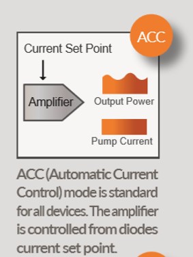
ACC mode - automatic current control: the EDFA pumping current is set by the user, and the EDFA automatically locks it to keep the pumping current constant. Even if the input optical power fluctuates, the pump current will not change in response, so the output power will also fluctuate. The EDFA does not interfere with this power fluctuation and the ACC mode is available for all EDFA models. Small signal EDFA amplifier, only ACC mode.
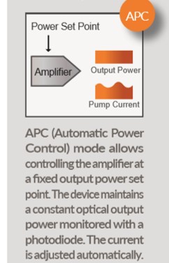
APC mode-automatic power control: The signal optical output power of the EDFA is set by the user, the PD automatically monitors and feedbacks the output power, and the EDFA controls and adaptively adjusts the pump to achieve the stability of the output signal. The advantage of APC mode is that when the input optical power fluctuates, the EDFA will reduce the fluctuation of the output power as much as possible, which is suitable for power type and line type EDFA.
Ease of understanding with the help of the following diagram
|
 |
|  |
4, There are many types of EDFA erbium-doped fiber amplifiers on the website, for example, single-wavelength EDFA, multi-wavelength EDFA, and pulsed EDFA, what is the difference between them? What are the advantages of pulsed EDFA over single wavelength EDFA?
Single-wavelength EDFA, multi-wavelength EDFA, and pulsed EDFA, although the principle is the same, are all laser-pumped erbium-doped fibers in the 980nm band to generate an optical gain in the C-band and L-band, optimized design and processing.
Single wavelength EDFA The main design of the product considers only a single wavelength signal input at the same time in the C-band or L-band and does not consider the application of simultaneous amplification of multiple wavelengths; in fact, multiple wavelengths can also be input to the amplifier at the same time, but the gain of different wavelengths in the C-band, the maximum may reach 3dB.
Multiwavelength EDFA The main design of the gain flat type product considers the simultaneous input of multiple wavelengths in the C-band at the same time, and the gain flatness of the simultaneous amplification of multiple wavelengths needs to be considered. The optimal gain flatness can be within 1.5dB by optimizing the design. However, it should be noted that the best flatness can be achieved when both the input optical power and the output optical power need to be fixed values; for example, for a certain model of multi-wavelength gain flat EDFA, the designed input optical power is -20dBm, and the input optical power is 20dBm, the gain flatness is ≤1.5dB; when the input optical power deviates from -20dBm or the output optical power deviates from 20dBm, the gain flatness may become larger;
Pulse EDFA Mainly for low repetition frequency (<1MHz), and narrow pulse width signal (<10ns), because such a pulse signal is easy to generate a high pulse when amplifying and exciting various nonlinear effects, resulting in spectral deterioration and pulse distortion, so the amplifier is in the While satisfying the power amplification, the optical nonlinear effect in the EDFA amplification process is minimized, the pulse distortion is reduced, and the signal-to-background ratio on the amplified signal spectrum is improved.
Click Here for more Single wavelength EDFA info. |
5, Can a pulse-type amplifier amplify a square wave pulse and keep the pulse shape unchanged?
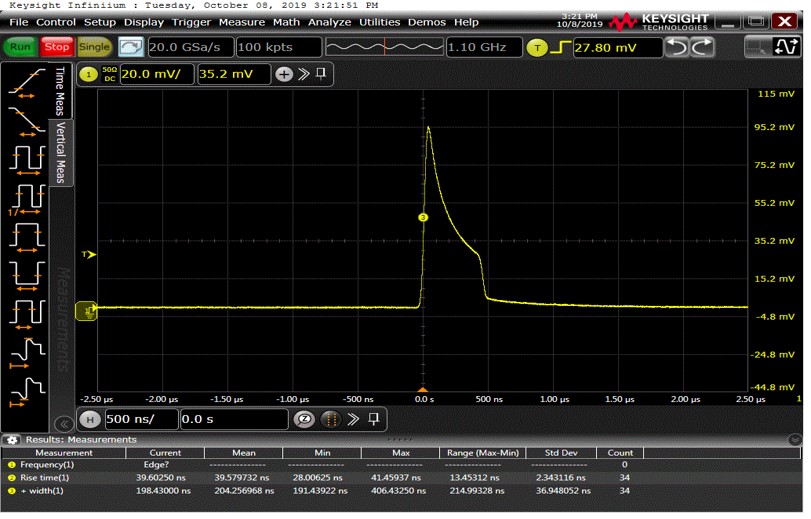
Although the pulsed amplifier is optimized for the pulsed laser signal, when amplifying the square-wave pulsed laser (pulse width>50ns) signal with a wider pulse width, due to the characteristics of the gain fiber, the leading edge of the signal pulse is given priority to gain the gain Amplification, the gain obtained in the middle and tail of the pulse is gradually reduced, so a square wave pulse with a flat top, after being amplified by EDFA, tends to appear in the shape of an upturned front of the pulse and a gradually reduced middle tail. This phenomenon cannot be eliminated, and the pulse The wider the width, the more obvious this phenomenon is (it can be understood that the upper-level ions consumed by the signal at the front of the pulse are not replenished in time, and the signal at the back of the pulse has already arrived, so the gain at the back of the pulse is gradually reduced). As shown in the following figure, the pulse waveform after 500ns pulse amplification and the pulse waveform after 40us pulse amplification can be seen them have top distortion, and the distortion of 40us pulse amplification is more serious.
|
 |
| 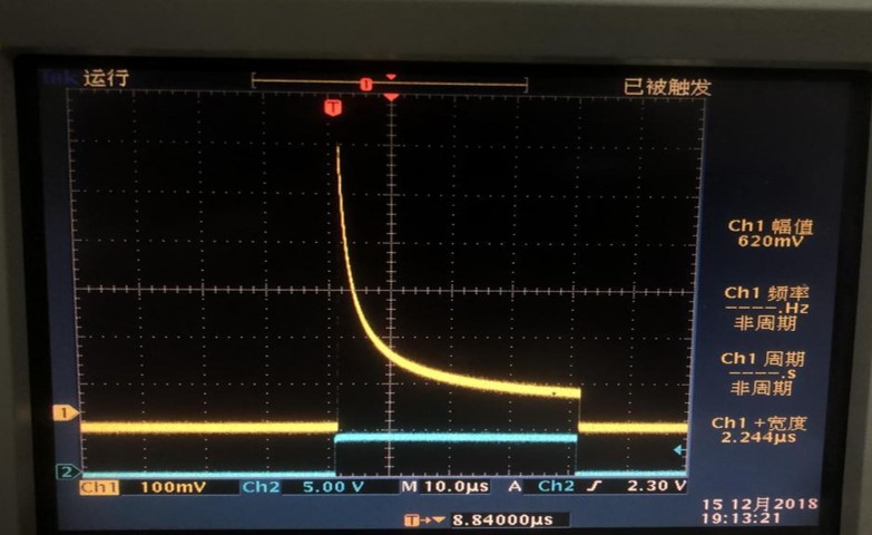 |
| (Above the blue laser pulse before amplification, the pulse width is 40us, the top is flat; the yellow is the amplified laser pulse, and the top is obviously uneven) |
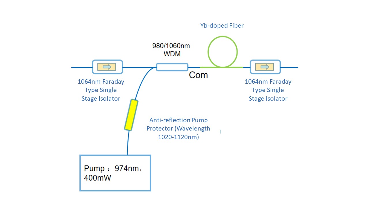
6, What is a pump protector? How do you choose one?
We found that some customers' 980nm pump lasers encountered no light at the beginning of use or when the frequency of use was very low. During the repair, we found that part of the reason was that the end face of the output fiber was burnt (the fiber connector was plugged and unplugged when the laser was output, or the end face of the fiber had an It is caused by turning on the laser when it is dusty), and another part of the reason is that the return light enters the pump laser chip, causing irreversible damage to the chip. In view of the high frequency of this situation, it is recommended to use a pump protector. The pump protector is a fiber-coated filter element that is usually added between the pump laser and the user's WDM to prevent signals generated by rare earth fibers. A small part of the light is pumped back through the WDM, causing the pump laser to be damaged. For the convenience of use, our 980nm pump laser products can integrate a protector inside the chassis. The device transmits the pump wavelength bidirectionally (910~990nm), does not transmit the signal light of the erbium-doped fiber (anti-reflection wavelength 1500~1600nm) or does not transmit the signal light of the ytterbium-doped fiber (anti-reflection wavelength 1020~1120nm), thereby protecting the pump laser, but the protector will bring 10~15% power loss. It should be noted that the pump protector required for erbium-doped fiber and ytterbium-doped fiber is not universal, so when purchasing a pump laser, please confirm with us whether a protector is built in the pump module and the specific anti-reflection wavelength of the protector. In addition, the protector has no one-way isolation effect on the 980nm pump wavelength, that is, the 980nm laser reflected along the output fiber can still return to the pump laser through the pump protector. If the pump needs to be isolated in one direction, the 980nm isolation can be added device. The use of the pump protector is as follows:
|
 |
7, What is a Raman amplifier? How to use it?
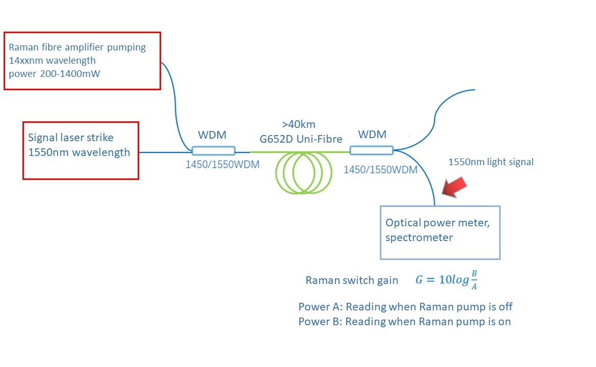
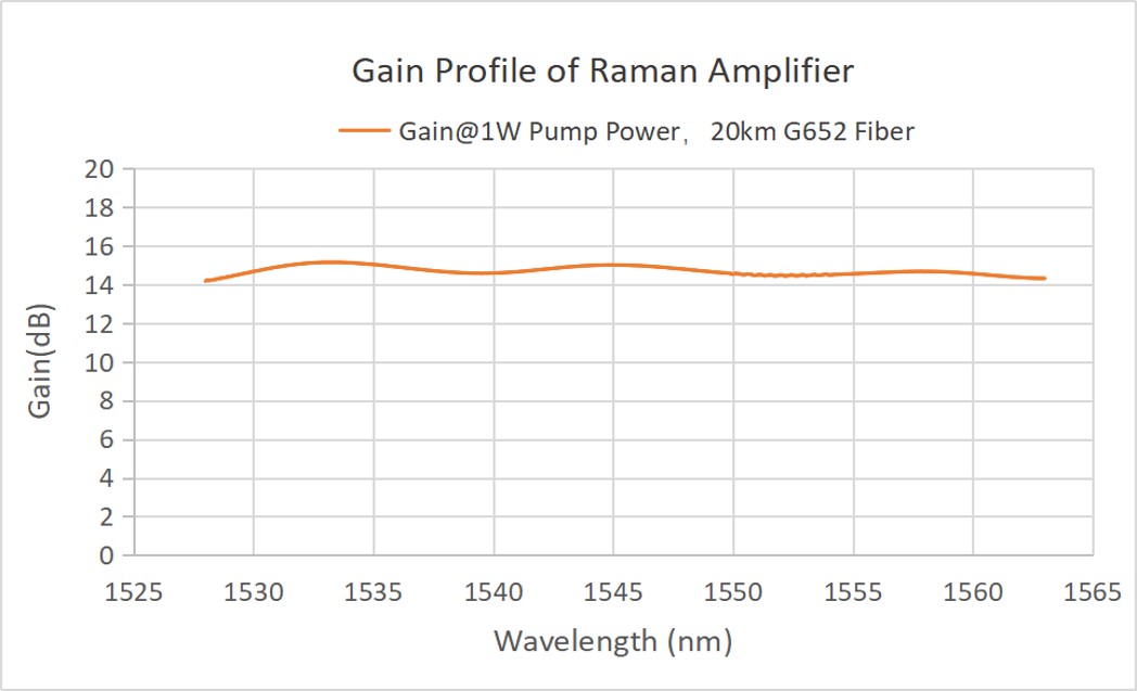
Please refer to the SIMTRUM website for the Fiber Raman Amplifier. The fiber Raman amplifier uses the Raman effect in the silica fiber to provide gain to the optical signal and realizes high gain and low noise amplification for the optical signal in the C or L band, which can effectively compensate for The attenuation of optical signals in long-distance optical fiber transmission is usually used in long-distance optical transmission communication systems, distributed optical fiber sensing, and dense wavelength division multiplexing optical transmission systems. For the C-band signal with a wavelength around 1550nm, a Raman pump laser with a wavelength of 1420~1465nm is generally used. The signal light and the Raman pump light simultaneously enter the long-distance transmission fiber through WDM, which constitutes a distributed fiber Raman Amplifier; for signals of multiple wavelengths distributed in the CL band, the Raman pump also needs to select multi-wavelength pumps from 1420 to 1500 nm to achieve flat gain, as shown in the figure below (multi-wavelength signals in the C-band, transmission length of 20km, ordinary single-mode Fiber, Raman pump wavelength 1425-1465nm, power 1 watt). The Raman amplifiers we provide are mainly Raman pumped lasers, wavelength division devices, and gain fibers that can be provided by users, and we can also provide them. It should be noted that the gain of the Raman amplifier refers to the comparison of the signal power at the receiving end of the system when the Raman amplifier pump is turned on and off, also known as the switching gain, such as the one-way communication system in the figure below, signal light and pump light. In the same direction transmission, the signal optical power is detected at the far end. |
One-way fiber optic communication
|
The Raman gain given in the product information is for a test system we built, using a 20km single-mode fiber, which is equivalent to an example demonstration. It does not mean that customers can use this pump to produce exactly the same gain in their own system. It may be larger than that in our data, or it may be smaller than ours. We do not have the final gain effect of the Raman amplification system built by customers. Guarantee (the gain depends on many factors in the system), customers choose different Raman pump power according to their own situation when placing an order; we only guarantee that the wavelength and power of the Raman pump conform to the contract or product data nominal parameter.
|
A Raman amplifier has been added to our user's case of distributed fiber optic vibration sensing system (schematic)
|
Distributed Fiber Optic Sensing 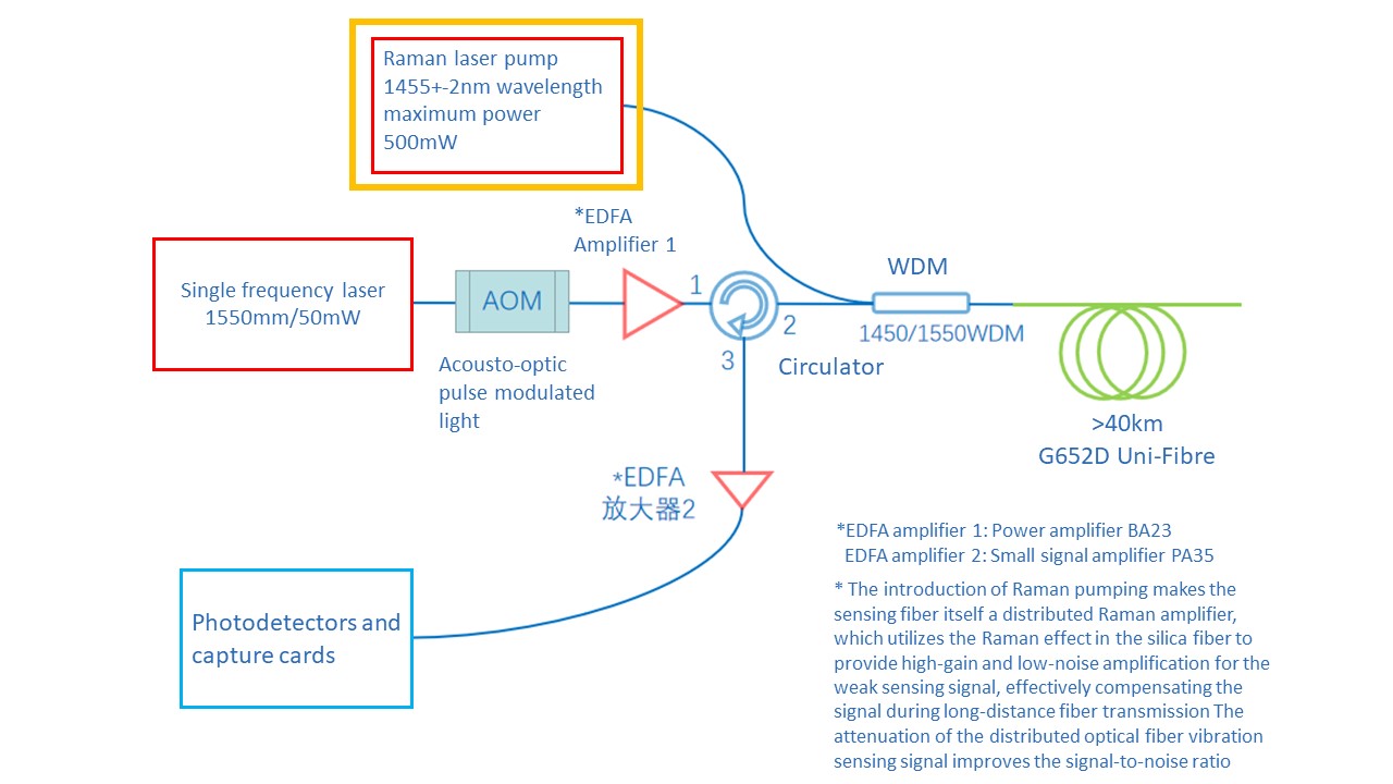
|