In the field of laser technology, the spatial size conversion of the laser beam is one of the most conventional operations. If the collimation of the beam is not considered, a single lens can be used to focus and diverge the beam. If you want to get a nearly collimated laser beam, the use of an optical expansion (contraction) beam system is the only solution.
Optical beam expansion systems are used in all-round of the laser field. For example, it is used to increase the light spot between the various stages of the laser amplifier to reduce optical damage. It can be used to optimize the fill factor. It is used to adjust the spot size in the nonlinear transformation to get the best conversion efficiency. And, this system is also used to make laser image transmission to ensure beam quality and can optimize the spot size and Rayleigh length in the focusing system, etc. It is almost everywhere.
This article provides some basic skills and methods for laser practitioners based on the laser beam expansion technology of the telescope principle. The basic context of the article includes the basic principle of beam expansion, debugging method, comparison of reflection type and refraction type, the criterion of laser collimation, and the adjustment method of the image transfer system.

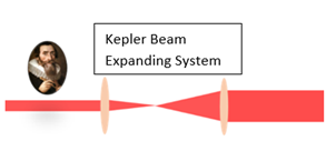
(a)

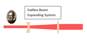
(b)
Figure 1. Two classic laser beam expansion systems. Note: This diagram is only a schematic. The selection of lenses in the actual beam expansion system needs to consider factors such as aberrations according to the actual situation, so it is not necessarily a simple single lens form.
1. Basic principles
The basic principle of the laser beam expansion system is very simple, everyone has already learned in the high school physics class. According to the type of lens group used, it can be divided into two categories: Kepler type and Galileo type. Figure 1 shows the Kepler beam expansion system, which is composed of two positive lenses. There is a common real focus between the lenses. Ideally, the distance between the lenses is the sum of the focal lengths of the two lenses.
Figure 2 is a Galileo-type beam expansion system, which is composed of a negative lens and a positive lens. The distance between them is the absolute difference between the focal lengths of the two lenses. From the aspect of the geometric structure, the space distance occupied by the Galileo type is smaller than that of the Kepler type, and there is an actual focal point in the Kepler type, which will break through the air under strong laser conditions, resulting in the spatial distribution of the beam and deterioration of the wavefront. So, in general, the Galileo type will be used more for laser beam expansion. The application of Kepler will be described in detail in the image transmission section below.
In addition, the reflection type (spherical mirror, cylindrical mirror, off-axis parabolic mirror) is often used to expand the laser beam. For example, in a strong laser, to avoid the nonlinear effects in the refractive beam expansion system, the reflection type is generally used. Beam expansion, but the spherical mirror reflection beam expansion system will introduce more aberrations, so sometimes it will use a high price, but no aberration off-axis parabolic beam expansion system. Therefore, if you want to choose a beam expansion system, you should take comprehensive factors such as price, aberration, and whether there are imaging needs into consideration.
2. Debugging methods and techniques
During the construction of the beam expansion system, the position and spacing of the two lenses are generally determined according to the design parameters. Simple plano-convex lenses are often used in beam expansion systems. At this time, you should first pay attention to determine the direction of the convex surface of the lens to make it face the direction of light incidence to reduce spherical aberration.
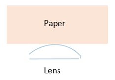
Tips for determining the convex surface: As shown in Figure 2, you can use a clean piece of hard paper with the edge close to the lens surface. If there are gaps on both sides, it means that it is convex, otherwise, it is flat, but you need to be careful not to scratch the lens.

Figure 2. Tips for determining the convex surface of a plano-convex lens
Follow the coaxial and over-center methods to ensure that the lens posture is correct. The light reflected from the surface of the lens is called a "ghost point". In a high-energy laser, the safety of components has a higher priority than the optimization of aberrations. The posture of the lens is generally artificially set away from the ideal posture to prevent damage to upstream optical components from the return light. During the adjustment process, an infrared card or an infrared night vision device can be used to determine the position of the ghost point and corresponding protective measures (such as the use of a light barrier).
Put the second lens in the same way, and then adjust its front and back position to ensure the collimated output of the beam. The judgment of collimated light will be explained in detail below. After collimation, if the measured distance between the two lenses deviates too much from the ideal situation, the reason may be that the incident light is not collimated, or it may be because the focal length of the lens is not selected properly (for example, when purchasing, you did not pay attention to selecting focal length with the corresponding wavelength).
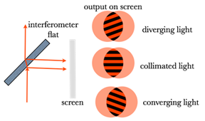
Besides, the judgment of beam collimation is generally measured by measuring two spot sizes at relatively long distances, but a more accurate and simple method is to use a Shearing Interferometer. As shown in the following figure, it is according to the degree of tilt of the interference fringe that determines the degree of collimation. However, it should be noted that this method cannot be applied to broadband light sources with extremely short interference lengths.

Figure 3. Interferometer to determine beam collimation
3. Image Delivery
The image delivery system generally uses a Kepler type positive lens combination to deliver the beam to the actual application position. the high-quality beam expansion is the most commonly used between the various stages of the laser amplifier, which can thereby avoid damage of the optical element from the diffraction structure by the free propagation. A spatial filter with a soft-edge diaphragm under vacuum conditions is often used with image transfer systems.

Figure 4. Image delivery system with spatial filtering