The SIMTRUM SVW1 is a user-friendly precision optical instrument with powerful analysis functions for all kinds of surface form & roughness parameters. With unique light source it could measure various precision parts with both smooth and rough surface. SIMTRUM SVW1 Optical 3D Surface profilometer is an ideal instrument for sub-Nanometer measurement of various precision parts. Based on the principle of white light interference technology, combined with precision Z-direction scanning module and 3D modeling algorithm, it contactlessly scans the surface of the object then establish a 3D image for the surface. A serial of 2D, 3D parameters reflecting surface quality of the object are obtained after XtremeVision software processes and analyzes the 3D image. | 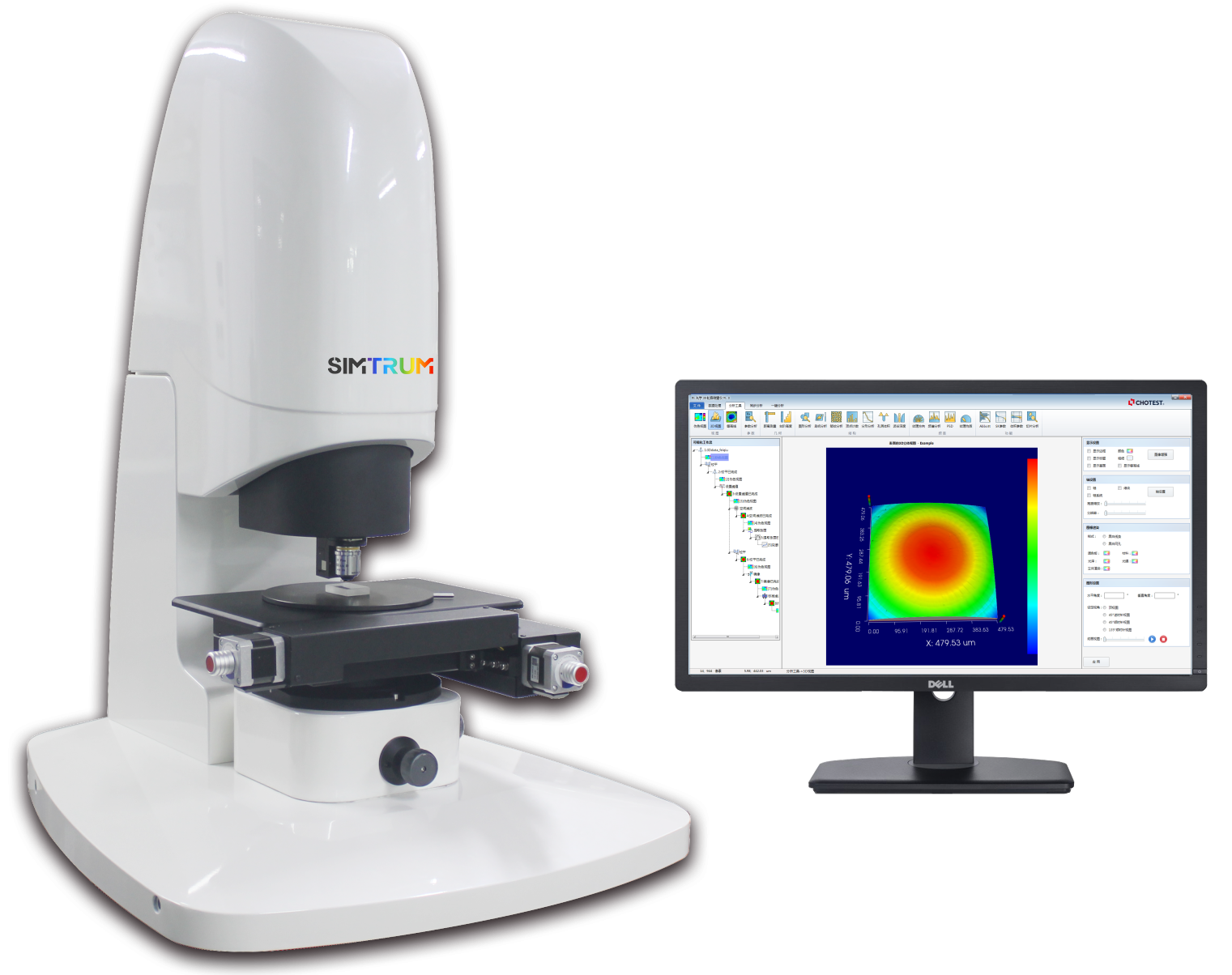
|
| For More Information please contact us: info@simtrum.com Product Brochure: Download |
Technical Parameters
| Model No. | SIMTRUM SVW1 | SIMTRUM SVW1-Pro |
| Light Source | Green LED |
| Video System | 1024 x 1024 |
| Standard Field of View | 0.98 x 0.98 mm |
Max Field of View
| 6.0 x 6.0 mm (Optional) |
| Lens Holder | 3 holes-manual |
| XY Object Table | Size | 320 x 200 mm | 300 x 300 mm |
| Moving Range | 140 x 100 mm | 200 x 200 mm |
| Loading Capacity | 10kg |
| Control Method | Motorized |
| Tilt | ±5°Manual |
| Z Azis Focusing | Moving Range | 100 mm |
| Control Method | Motorized |
| Max Scanning Speed | 45 µm/s |
| Scanning Range of Z Axis | 10 mm |
| Resolution of Z Axis | 0.1 nm |
| Lateral Resolution | 0.1µm |
| Stage measurement | Uncertainty | 0.30% |
| Repeatability | 0.08% 1σ |
| Size | L900 x W700 x H604 mm | L900 x W700 x H700 mm |
| Weight | < 150 kg | < 160 kg |
| Power | AC100 ~ 240 V, 50/60 Hz, 4A, 300W |
Remark: Performance parameters are tested by using a 4.7µm precision master stage gauge in lab according to ISO 4287 and ISO 25178
Standard configuration
|
| Optional Configuration
|
1) Host machine
|
| 1) Parfocal objective lens: 2.5X, 5X, 10X, 50X,100X
|
2) High speed camera
|
| 2) Optical zoom: 0.75X, 1
|
3) Optical Zoom: 0.5x
|
| 3) Vacuum chuck: 4", 6" or 8
|
4) Parfocal Objective lens :10x
|
| 4) Motorized 5 holes turret
|
5) Motorized X & Y object table
|
|
|
| 6) 4.7μm stage master gauges |
|
|
7) Joystick
|
|
|
8) XtremeVision software with automatic switching function
|
| Environmental Requirement |
9) Electrical control box
|
| 1) Operating environment: No strong magnetic field |
10) Computer(WIN10) and 24" monitor
|
| 2) Working temperature:15℃~30℃, fuctuation <2℃/60min |
11) Accessory suitcase
|
| 3) Relative humidity: 5%~95% RH, no condensation
|
12) Portable inflating pump
|
| 4) Environmental vibration: VC-C or better |
13) User Manual and Product Certificate
|
| 5) Pressure supply: 0.6Mpa oil-free, water-free, 6mm diameter of hose
|
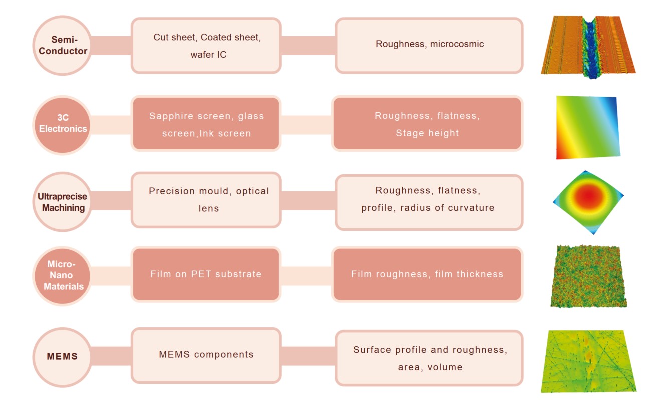
Application
It is used for measurement and analysis of surface roughness and profile of precision components from industries of semi-conductor, 3C Electronics, ultraprecise achining, optical machining, micro-nano materials, micro-electro-mechanical system.
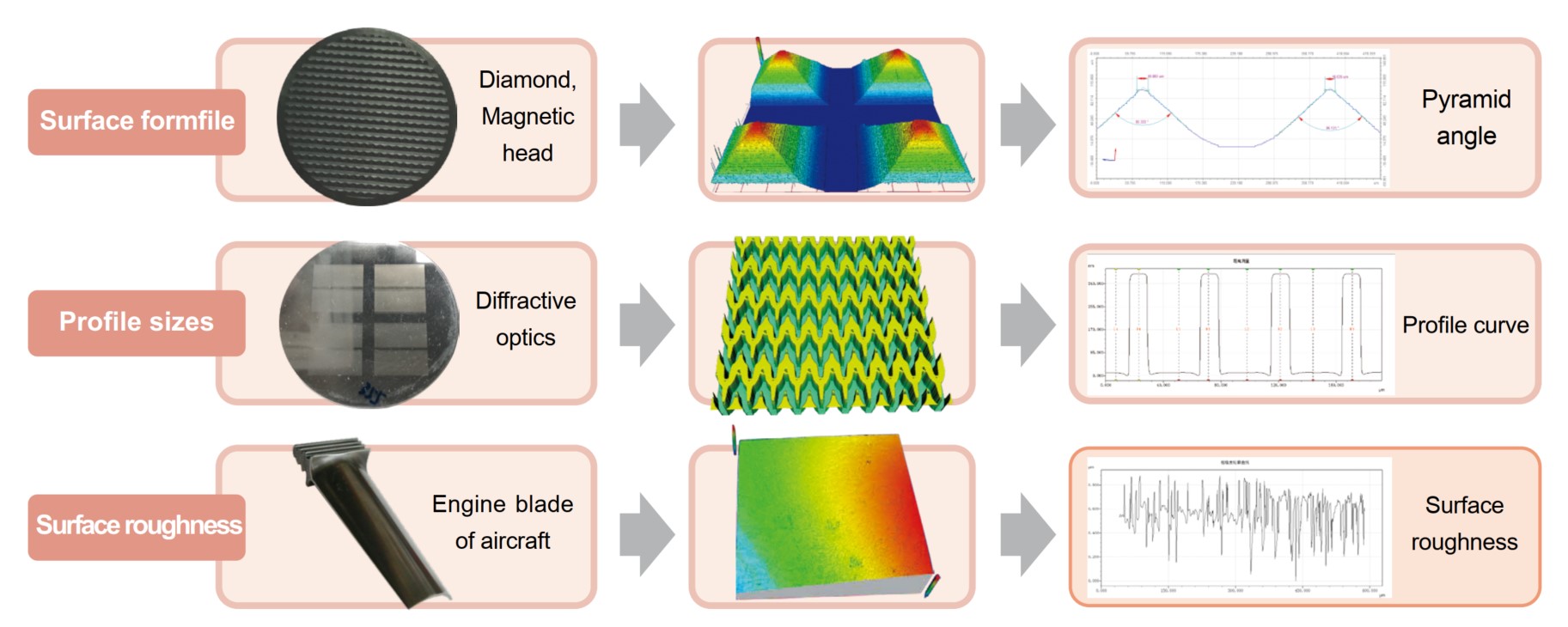
Application Case
Measurement and analysis for various products, components and materials`surface form and profile characteristics, such as flatness, roughness, waviness, appearance, surface defect, abrasion, corrosion, gap, hole, stage, curvature, deformation, etc.
XtremeVision 3D Software
Integration software: Measurement and analysis are operated in the same interface; With pre-set analytic parameters, the software automatically generates easurement data, and achieves rapid CNC measurement.
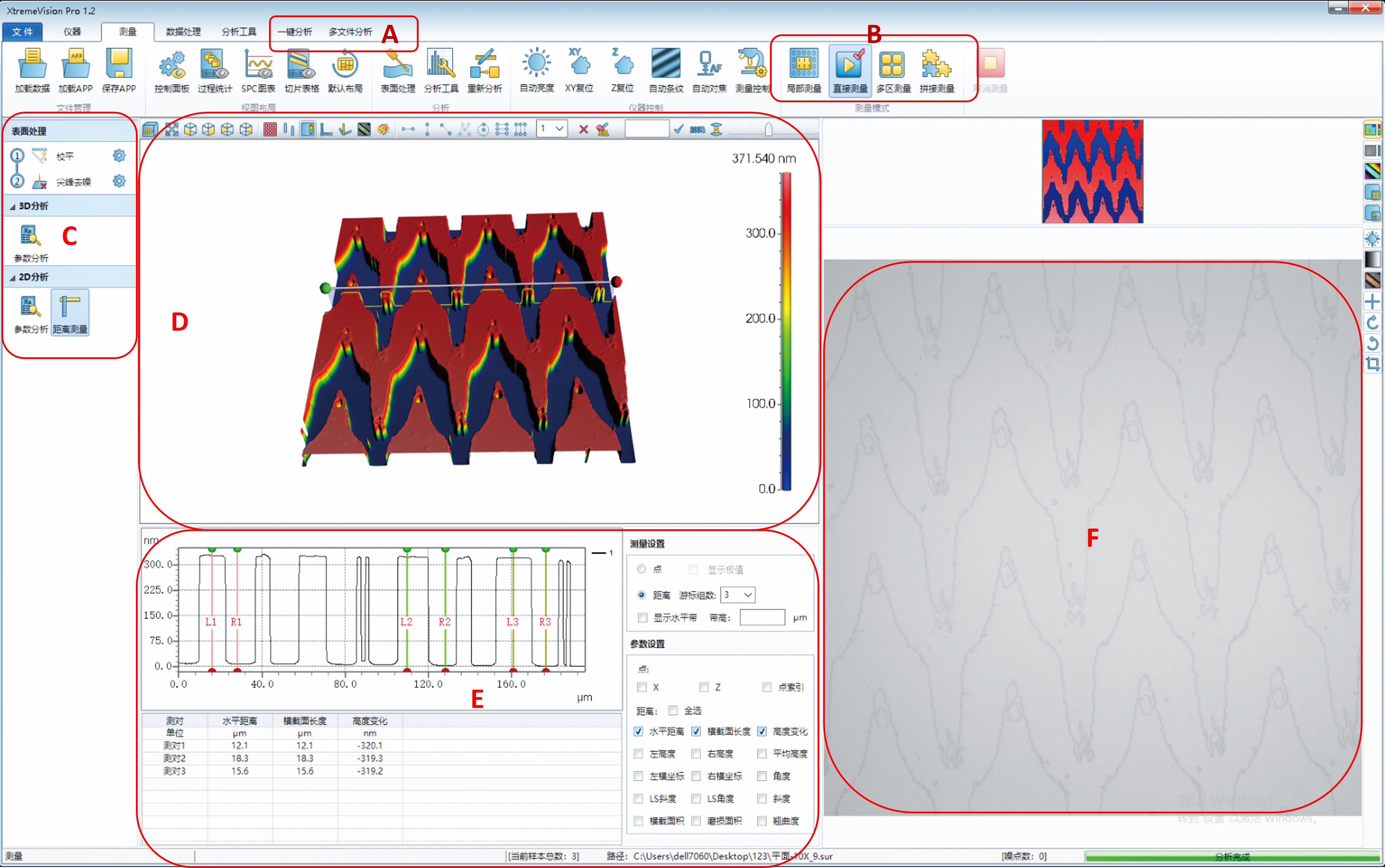
|
| A. After set analytic program, more than 10 files can be analyzed by one click, finally data result and statistical graph are generated automatically. B. 1) Auto Measurement: After set measuring ranges & points and related parameters, multi-area can be measured. 2) Stitching Measurement: After set the measuring range and parameters, large area could be measured by one click automatically.
3) Partial measurement: Can select any area in field of view to be measured. C. Configure parameters: After pre-set leveling, filtering and 2D&3D parameters, data could be measured and generated automatically according to pre-set program.
D. 2D, 3D Image operating zone.
E. Analysis window: Display the curves and data generated by present analysis tool.
F. Real-time video window. |