The focus of this article is the challenges faced with beam alignment. Due to the Covid-19 circuit breaker, we've spent some time out of the lab. As we return back to work, we're introducing a tutorial network and online resource for potential students, researchers and lab staff.
Tags: Lasers, Alignment, Optics, Tutorial
Reflector adjustment utilizes reflectors to achieve the deflection of the optical path. This article should give
you a basic understanding of the theory, concepts and methodology to this
process.

Figure 1. Entry level of optical path adjustment
Figure 1 shows the laser path of the basic optical setup with the key requirement of passing through points A and B. Over long distances, alignment of the path is important. Good practices include:
1. Increase the distance between AB to improve the accuracy of the adjustment.
2. Diaphragm A should be placed as close as possible to M2, such that it can be adjusted in one or two rounds, which would greatly improve efficiency.
This simple dual-reflector structure uses two reflectors, namely M1 and M2, to determine the light path AB. After everything has been executed, a clear optical path through AB should be seen. This will confirm your adjustment to be successful.
Can this be improved?
Apparatus has been designed to simplify this process. Not only will it greatly reduce the amount of time spent determining the light path, it is found to be a much safer option compared to manually adjusting reflectors which are the cause of many safety hazards. This method will determine the height and horizontal position of the optical path with minimal adjustments.
Highly recommended for modulating light, the laser leveling tool was originally used in construction sites, and has now become the mainstay in all laser labs.
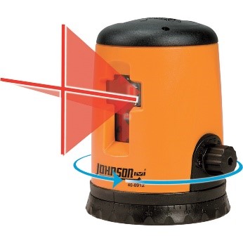
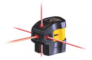
Figure 2. Horizontal reticle: linear (left), dotted (right)
In the adjustment process of the optical path, the horizontal reticle (tripod or lifting table) must first be adjusted to a suitable height. The vertical reticle is then transmitted to the design direction (general along the hole center of the optical platform), before starting on your own adjustments.
Laser Alignment in a vacuum
Certain setups require isolated systems (in vacuum sealed setups or where high beam energies are used) so making spontaneous adjustment are not ideal - However, Laser alignment is still achievable. The method used in Figure 3 is further discussed on our website.

Figure 3. Enhanced optical path adjustment: near and far field imaging
Additional benefits of using this method include:
1. The directional change of the optical path can be monitored in real time without changing the optical path in actual work
2. At the same time, it can also be equipped with an automatic calibration system for real-time feedback and adjustment
3. Suitable for the adjustment and monitoring of the optical path under vacuum conditions, but it needs to be equipped with a vacuum adjustable knob.
4. High-end, suitable for showing off.
Recommendations for using these skills:
1. The surface of M2 must be strictly imaged on C1. The imaging system is designed in advance. A business card (or imaging card) can be placed on the surface of M2. Use a flashlight to illuminate the object surface and gradually move C1 until you get a clear image
2. C2 must be in a focused position, the quality of the focus need not be too tangled, only the center is required
3. Determine the focal length of L1 and L2 according to the chip size of the CCD, and use a positive lens, otherwise the image cannot be formed
4. In terms of cost, the lens, beam splitter, CCD camera and beam splitter in the optical path is relatively cheap
5. In vacuum conditions, the time when the CCD is energized must be strictly controlled to avoid damage to the camera from excessive heat.