It is well known that after a non-centrosymmetric & non-linear birefringent crystal (or optical medium) is applied with a directed electric field, its birefringent optical properties will change with the modulation of the electric field. To remember the famous German scientist Friedrich Pockel, this electro-optic effect with a linear relationship between the refractive index and the electric field is called the Pockels effect. The nonlinear crystal device with a modulated voltage is generally called the Pockels cell. And it is widely used in electro-optic Q-switched lasers and pulse selectors. Non-linear crystals widely used in Pockels cells include KD*P, BBO, LiNbO3, KTP, etc. This article will provide a more detailed introduction to the application properties of this device from the technical level, based on Q-switching and pulse selection.

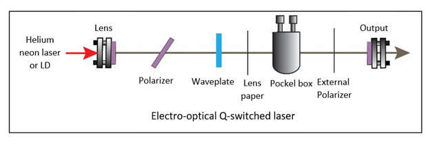
Figure 1. Electro-optic Q-switched laser
1. Brief introduction of the working principle
(1) Electro-optical Q-switching
A typical electro-optical Q-switched pulse laser (see Figure 1), its core components include a laser cavity, electro-optic modulation system, polarizer, etc. When the Pockels cell is at zero voltage, the laser cavity is in a state of high loss and low Q value due to the presence of a quarter-wave plate in the cavity; on the contrary, when an external voltage is applied, the pulse travels back and forth through the Pockels cell, The polarization is reversed by 90 degrees. At this time, the laser cavity is in a state of low loss and high Q value, which can realize laser oscillation. In order to achieve the expected experimental results, the posture of the Pockels cell needs to be precisely adjusted during this process to ensure that the laser propagation direction is strictly parallel to the optical axis of the crystal to achieve the effect of strictly inverting the polarization by 90 degrees. Otherwise, the best effect of Q-switching will not be completed, and even the output energy will be reduced, and the time quality will be degraded, which will cause damage to the optical components.

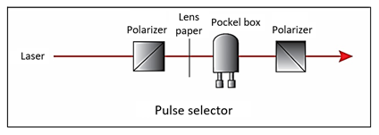
Figure 2. Pulse selector
(2) Pulse selection
Using the combination of Pockels cell and Glan prism, it is also possible to adjust the pulse repetition frequency or select the specified pulse. For the specific principle, refer to Figure 2. The pulse sequence with high repetition frequency passes through the Pockels cell. By controlling the repetition frequency, time delay and pulse width of the Pockels cell voltage signal, the time window of the voltage falls on the required signal pulse. In this process, it is necessary to ensure that only the polarization direction of this pulse changes, while the polarization of other pulses does not change. Using a polarization selection device such as a Glan prism, the required pulse can be accurately selected.
2. Safe operation
(1) Personal safety
It is strongly recommended to wear laser protective glasses during the dimming process. Especially during the adjustment of the polarizer, the reflected beam may be reflected in the vertical direction. In terms of safety, the beam should be set to reflect downward as much as possible in this operation. At the same time, the use of safety light barriers can also avoid potential eye damage.
(2) High voltage safety
• Try to avoid live operation of Pockels cell
• During normal operation, the top cover needs to be closed to prevent accidental contact with the high-voltage circuit.
3. Pockels cell adjustment techniques
(1) Propagation of divergent beam in a birefringent crystal
Based on the anisotropic characteristics of birefringent crystals, the phase change experienced by the diverging beam during its propagation is angularly symmetric. If a polarizer is placed behind it, interference fringes will form at multiple angles. In this process, it is necessary to pay special attention to two special directions, the o-axis, and the e-axis of the crystal. The polarization of the beam propagating in these two directions does not change, and the final spot distribution is a typical Isogyre shape. The core technique of Pockels adjustment is to generate a divergent beam, and then use the relative position or symmetry distribution of the transmitted light spot as a reference to measure whether it is adjusted properly.

Figure 3. Two typical Isogyre shapes
Distribution without orthogonal polarizers (left)
Distribution behind orthogonal polarizers (right)
(2) Pockels cell adjustment in Q-switched laser
As shown in Figure 1, when installing or optimizing a Pockels cell in a Q-switched laser:
• First ensure that the light beam passes through the center of the Pockels cell as much as possible to avoid cutting light.
• Second, use a He-Ne laser or LD light source to obtain a divergent beam through a lens paper.
• Place a polarization selection device orthogonal to the polarizer in the cavity behind the Pockels cell. Place a card behind the Pockels cell. If it is not directly observed through the orthogonal polarizer, the left picture in Figure 3 can also be used as the basis for judgment. Adjust the two knobs of the Pockels cell (Pitch and Yaw) to directly transmit the light in the center of the crosshairs. If you observe behind the orthogonal polarizer, the right image in Figure 3 is used as the basis for judgment. Similarly, you can adjust the Pitch and Yaw knobs so that the entire orthogonal pattern is as symmetrical as possible, and the crosshairs are symmetrically distributed.
• After adjusting Pockel's posture, don't forget to remove or block the external laser light source, and then remove the additional lens paper and polarizer.
• After the laser is running, the posture of the Pockels cell can be further adjusted to ensure that no laser is generated in the cavity when the Q-switched voltage is applied zero.
• The output laser energy and pulse shape can be optimized by adjusting the voltage and time delay of the Pockels cell.
(3) Pockels cell adjustment in the pulse selector
The Pockels cell attitude adjustment method in the pulse selector is the same as the above method, and the actual working laser can be used without the help of an external light source. Since there are already two orthogonal polarization elements, only one lens paper is needed.
• Before installing the Pockels cell, adjust the two polarizers to achieve full orthogonality.
• Strictly follow the above steps to perfectly display the Pockels cell posture.
• Check the adjustment effect: you can observe the laser energy parameter behind the second polarizer when no voltage is applied to the Pockels cell. At this time, it should be in the weakest state.
References:
[1] Thibault Dartigalongue and François Hache, "Precise alignment of a longitudinal Pockels cell for time-resolved circular dichroism experiments," J. Opt. Soc. Am. B 20, 1780-1787 (2003)
[2] "POCKELS CELL ALIGNMENT IN A Q-SWITCHED LASER"
[3] Nisperuza, Daniel & Botero, G & Bastidas, Alvaro. (2010). Precise alignment of a longitudinal Pockels cell for Q-switch operation Nd:YAG laser. Revista Cubana de Física. 27. 63-65.