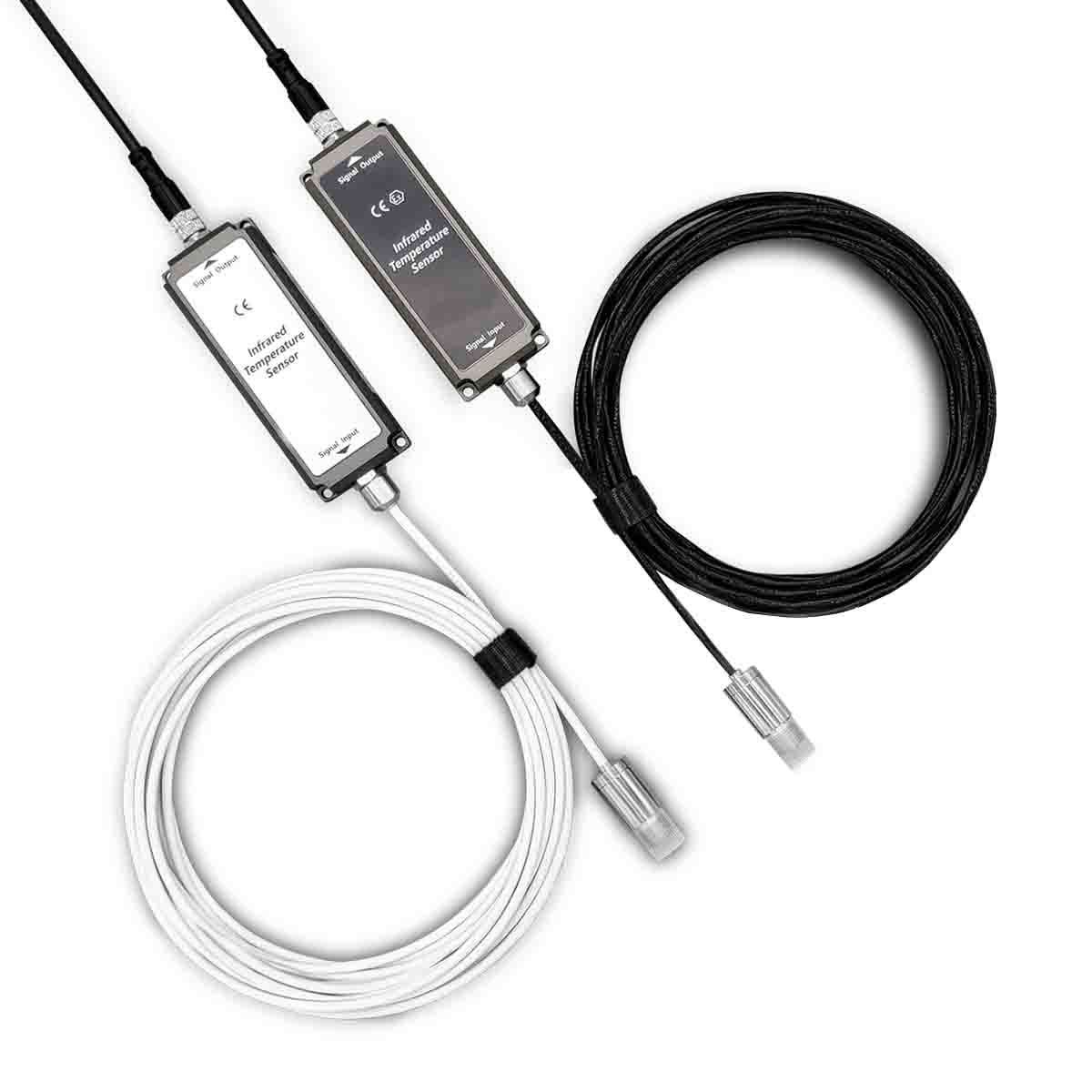
Confocal Raman Microscope
Handheld Confocal Raman Skin Analyzer
Spinning Disk Confocal Microscope
Laser Point Scanning Confocal Microscope
Research Line Scan Confocal Microscope
Industry Line Scan Confocal Microscope
More
Auto-Fluorescence Microscope
Compact Multi-channel fluorescence microscope Module
Four-channel Single-mode /Multi-mode laser(405-640 nm)
Silicon photomultiplier(SIPM)(300-950nm)
Photomultiplier Tube (Module)(160-900nm)
Motorized Filter Wheels
MMF laser speckle reducers & beam homogenizers
TCSPC System for SPAD (APD) Testing Solution
Fiber Spectrometers (200nm to 2.5um)
Raman Spectrometer 532/785/1064nm
X-Ray/XUV/VUV Spectrometers (1-300nm)
FT Infrared Spectrometer(900-16000nm)
Hyperspectral Camera (220nm-12.5μm)
Multi-Spectral Camera (400-1000nm)
Single Photon Detector (SPD)(200-1700nm)
Photomultiplier Tubes (PMT)(160-900nm)
Photodiode Detector (PD)(320-1700nm)
Pyroelectric Infrared Detectors (2-12um)
Single-Photon Avalanche Diode Array
UV-VIS Beam Profiler(190-1100nm)
VIS-NIR Beam Profiler(350-1750nm)
Mid-infrared Beam Profiler(2-16μm)
Compact Beam Profiler(190-1100nm)
Terahertz Beam Profiler
Scanning Slit Beam Profiler
Photodiode Power Sensors 250-2500nm
Power Meter Console
Integrating Spheres (10mm-100mm)
Power Meter Adaptor & Accessories
Thermoelectric laser power meter(0.19-25 μm)
Photoelectric power meter(200-1100nm)
VUV/UV Spectrograph
Standard Single Grating Monochromator
Hi-Res Single Grating Monochromator
Double Grating Scanning Monochromator
Triple Grating Scanning Monochromator
Hi-Res Triple Grating Monochromator
Micro laser Doppler vibrometer DC~2.5MHz
Laser Doppler Vibrometer 0.1Hz to 5Mhz
LIV Test Systems for Laser Diode / LED
White Light Interferometer
Optical Test Measurement System
RF Test Measurement System
Point confocal displacement sensor
Linear confocal displacement sensor
CW Pigtail Laser Diode (400-1920nm)
CW Laser Diode Module (375-785nm)
CW Single Channel Lasers (365-1570 nm)
CW Multi-Channel Lasers (375-808nm)
CW Narrow Linewidth Diode Laser
External Cavity Tunable Diode Laser (399-1260 nm)
Nanosecond Pulse Fiber Laser(1064-2μm)
Picosecond Pulse Fiber Laser (266nm-2μm)
Femtosecond Pulse Fiber Laser (515-1570nm)
CW & QCW Fiber Laser System (405nm-2μm)
CW Narrow Linewidth Laser(780nm-2μm)
C-Band Tunable Laser (1529 -1567nm)
L-Band Tunable Laser (1554 -1607nm)
Supercontinuum Fiber Lasers 450-2300nm
2 μm CW Wide Tunable Laser (1900-2000 nm)
Femtosecond OPA (650 - 2600nm)
Short-pulse OPA (650 - 2600nm)
Erbium Doped Fiber Amplifier
Ytterbium Doped Fiber Amplifier
Thulium-Doped Fiber Amplifier
Semiconductor Optical Amplifier
Fiber Raman Amplifier
EUV Light Sources(58-130nm)
VUV Light Sources(115-400nm)
ASE Light Sources (830-2000nm)
Microscopy Imaging LED Sources 360-780nm
Collimated LED Sources (265-1450nm)
Fiber-Coupled LED Sources (265-940 nm)
Standardized Repetition Locking Optical Combs
Fully Locked Optical Frequency Combs
Asynchronous Optical Sampling Light Source
Optical Frequency Comb Accessories
Maskless Lithography UV Laser Writer
Light Field Sythesizer
Hollow-Core Fiber Compressor
High Powered Hollow-Core Fiber Compressor
Ultra-High Contrast 3rd-Order Autocorrelator
Coherent Ultrabroadband XUV Light Source
Terahertz Quantum Cascade Lasers(1-4.5Thz)
MIR QCL Turn-Key System (3-13μm)
MIR Packaged QCL(4-9.7μm)
MIR QCL Chips(4-12μm, Package Customizable)
Compact Multi-channel fluorescence microscope imaging module
Fluorescence Upright / Inverted Microscope
Biological Upright / Inverted Microscope
Phase Contrast Microscope
Dark Field Microscope
Polarizing Microscope
Metallographic Upright / Inverted Microscope
Smart 3D Stereo Microscope
USB Digital Microscope With Platform
Built-in Digital Microscope
Plan Apochromatic Objective
Industrial Plan Objective
Biology Plan Objective
Microscope CCD Camera (VIS-NIR)
Microscope CMOS Camera (UV-NIR)
UV & NIR Enhanced CMOS Camera
Hyperspectral Camera for Microscope
Multispectral Camera For Microscope
Microscope Light & Lamp
Soft X-Ray BSI sCMOS Camera (80-1000eV)
High-Speed sCMOS Camera
High Sensitivity sCMOS Camera
38M Pixel large Format sCMOS Camera
Compact BSI/FSI sCMOS Camera
Intensified CMOS Camera (200-1100nm)
Full Frame CCD Camera for UV VIS NIR
Full Frame CCD Camera for VUV EUV X-ray
Full Frame In-vacuum CCD Cameras
Large Format In-vacuum CCD Cameras
HDMI Color CMOS Camera (Monitor)
High Speed Line Scan Camera
Large Format Camera
High Speed Large Format Camera
Frame Grabber
Infrared Pyrometers (-40-3000C)
Linear Array Infrared Thermal Imager
Matrix Array Infrared Thermal Imager
Blackbody Calibration Sources -15 to 1500°C
SWIR Camera(400-1700nm) InGaAs CMOS
SWIR Camera(900-2200nm) InGaAs CMOS
Mid-Wave Infrared Camera (MWIR)
Long-Wave Infrared Camera (LWIR)
Solar Blind UV Imaging Module 240-280nm
UV-VIS Online Monitoring Module
UV-VIS Dual Channel Camera
UV-VIS-IR Triple Spectral Fusion Camera
Ultraviolet Camera for Drone
Free Space Acousto-Optic Modulators (AOM)
Fiber Coupled Acousto-Optic Modulators
Free Space Acousto-Optic Tunable Filter
Fiber-coupled Acousto-optic Tunable Filter
Acousto-Optic Q-switch (AOQ)
Acousto-Optic Frequency Shift (AOFS)
Electro-optical Amplitude Modulator
Electro-optic Phase Modulator
Time-Correlated Single Photon Counting (TCSPC)
Ultra-fast Pulse Generator for TCSPC
Phase Spatial Light Modulator
Transmission Amplitude SLM
Reflection Amplitude SLM
Digital Micromirror Device (DMD)
Pulsed Voltage
Pulsed Current
General Purpose Pulse Generators
Medium and High Voltage Pulse Generators
High Speed Impulse Generator
Very High Speed Pulse Generators
Function Generators
Pulse Amplifiers
Single-channel Lock-in Amplifier
Dual-channel Lock-in Amplifier
Narrowband Tunable Filter
Broadband Tunable Filter
Bandpass Tunable Filter
TPX / HDPE Terahertz Plano Convex Lens
Off-Axis Parabolic Mirrors
Terahertz Hollow Retro Reflector
Terahertz Metallic Mirrors
ZnTe / GaSe Terahertz Crystals
Terahertz Beam Expander Reflection
Waveplates
Optical Isolator
Optical Polarizers
Beamsplitter Plate
Beamsplitter Cube
Dichroic Beamsplitters
Ultrathin Beamsplitter Plate
Bandpass Filters Fluorescence Microscope
Filters for Raman Spectroscopy
Narrow Filters for Laser
Filters for FISH
Filters for TIRF Microscope
Filters for FRET Microscope
Laser Crystals
Nonlinear Optical Crystals
Birefringent Crystals
Optical Crystals
Electro-optical Crystals
Micro-Channel Plate (MCP)
Micro-Channel Plate Assembly (MCP)
Fiber Optic Plates (FOP)
Micro Pore Optics
X-Ray Collimators
Hybrid Fiber Components
Electrically Adjustable Optical Delay Line
Manually Adjustable Optic Delay Line
Optical Circulator
FA Lens
Zoom Lens
Telecentric Lens Series
Optical Heating & Cryo Stage
Electrical Probe Temperature Stage
Adjustable Electrical Probe Station
In-situ Tensile Heating & Cryo Stage
SEM/XRD Heating & Cryo Stage
Live-Cell Incubator Stages
Single Axis Motorized Piezo Stage
XY Motorized Piezo Stages
Multi Axis Motorized Piezo Stages
Vacuum Non-magnetic Piezo Stage
Nano Electric Actuator
XY Stepper Motor Stages
XYZ 3 Axis Stepper Motor Stages
XY Microscope Piezo Stages
XY Microscope Linear Motor Stages
Motorized Filter Wheels Mount
FWR Motorized Filter Wheels
Manual Filter Wheels
Manual Filter Wheels Mount
13mm Linear Stages
25mm Linear Stages
Rotation and Tilt Stages
Rack and Pinion Stages
Vertical Axis Stages
2-Axis Stages
Solid Vibration Isolation Optical Table
Pneumatic Optical table
Pneumatic Optical Table With Pendulum Rod
Desktop Pneumatic Optical Table
Honeycomb Optical Breadboard
Lens Mounts
Mirror Mounts
Filter Mounts
Unlike the "direct signal processing within the probe" of integrated devices, the separated main unit can be far away from harsh environments such as high temperatures, dust, and vibration. It precisely amplifies, filters, linearly corrects, and performs data operations on electrical signals, and finally outputs the temperature value through the display screen. It simultaneously supports analog (4-20mA), digital (RS485/Modbus) and other signal outputs, facilitating integration into industrial control systems (such as DCS, PLC) for automated monitoring.
The core advantages of this equipment are mainly reflected in its environmental adaptability and application flexibility: On the one hand, the temperature measurement probe can be designed with high-temperature resistant materials and directly installed in areas near heat sources such as kilns, smelting furnaces, and high-temperature pipelines, while the main unit can be installed in normal temperature and low-interference environments such as control rooms and operation rooms. This not only ensures the temperature measurement accuracy of the probe but also extends the service life of the core components of the main unit. On the other hand, the separation distance between the probe and the main unit can be flexibly adjusted according to the demand, which can cover the "long-distance and high-risk" temperature measurement scenarios that are difficult for integrated equipment to reach, such as temperature measurement in the furnace of large thermal power generation units, surface temperature monitoring of steel continuous casting molds, and high-temperature area inspection of chemical reaction vessels.
Parameter
IM-ST-IRP2
IM-ST-IRP8
Supply voltage
12~24V DC
Measurement Accuracy *1
Standard: ±1.5℃/1.5%, some models: ±1℃/1%
Repeatability Accuracy *2
±0.75℃/0.75%, for some models: ±0.5℃/0.5%
Max. temperature measurement range *6
-40~100℃
-40~180℃
Temperature resistance of the probe
The probe cable is heat-resistant
200℃
260℃(300℃/450℃ Optional)
Min. spot diameter
7mm @ 50mm
Optical resolution
10:1/20:1 is optional, with 90% energy
Temperature coefficient *3
0.1K
Spectral range
8~14um
Simulated temperature resolution *4
0.1℃/0.1%
Digital temperature resolution *5
0.01℃
Response time (95%)
50~5000ms(Adjustable)
Emissivity
0.1~1.5(Adjustable)
Transmittance
Output signal processing
Mean, median, quantile, peak hold, valley hold
Supporting software
SensIRTS
Output method
Simultaneous digital and analog output (customizable for communication output only)
Analog output specification
0-20mA, 0-10V, 0-5V
Analog output load
Current output (max) : 500Ω; Voltage output (min) : 10KΩ (recommended above 30KΩ)
Stabilization time
10min
Digital output mode
RS485/Modbus
Alarm range setting
Digital setting
Alarm output
Digital output
Outgoing line specification
6 lines (default), 4 lines (communication signal only)
Probe wire length
3 m (default), 4/5/8/10 m, customizable
Output cable length
2 m (default), 1/3/5/10 m, customizable
Operating temperature range of the electronic box
-40~85℃
Storage temperature range
Relative humidity
0-95% no condensation
Earthquake resistance
10~150Hz, 1.5mm double amplitude, 2 hours for each of the XYZ axes
Impact
50G, 10 times in each direction of the XYZ axes
Installation dimensions
Probe M12×1, electronic box: 35mmDIN rail mounting
Shell material
SUS 316
Protection grade
IP65
Explosion-proof mark
Exia ⅡC T6 Ga
Special features
This model allows users to customize the temperature range of the analog output within the specified model specification range. For instance, if a model with a 0-300°C range is selected, the user can define the analog output range as 20-120°C in the SensIRTS software. Then, the 0-20mA output corresponds to 20-120°C, thereby enhancing the resolution of the analog output and facilitating the sensor to play a greater role within the range specified by the user.
Remarks
[1][2] The larger one was measured when the ambient temperature was 23±5℃ and the target object was a standard blackbody at 100℃. Some high-precision models need to be realized with accessories.
[3] It was calculated by measuring 100℃ standard blackbody at ambient temperatures of 40℃ and 80℃ respectively.
[4] Resolution of analog output.
[5] The digital resolution obtained through software or digital communication is the version at the time of release. Any changes will not be notified separately. The latest information on the official website shall prevail.
Temperature measurement range code
Code
T range
A
-40℃
F
45℃
L
150℃
R
400℃
B
-20℃
G
64℃
M
180℃
S
500℃
C
0℃
H
80℃
N
T
600℃
D
16℃
J
100℃
P
250℃
U
800℃
E
25℃
K
120℃
Q
300℃
V
1000℃
For example: AR indicates that the temperature measurement range is: -40 to 400℃. BV indicates that the temperature measurement range is: -20 to 1000℃
Note: The temperature measurement range is not an arbitrary combination. The method of taking values is shown in the selection reference table.
Model
Temperature measurement range
Output
Configuration information
IM-ST-IRP2-AJ
RS485&4-20mA
3m probe wire, 2m power cord
IM-ST-IRP2-CJ
0~100℃
IM-ST-IRP2-AN
-40~200℃
IM-ST-IRP2-CN
0~200℃
IM-ST-IRP2-AQ
-40~300℃
IM-ST-IRP2-CQ
0~300℃
IM-ST-IRP2-AS
-40~500℃
IM-ST-IRP2-CS
0~500℃
IM-ST-IRP2-AW
-40~1200℃
IM-ST-IRP2-CW
0~1200℃
IM-ST-IRP8-CJ
3m probe wire, 2m power cord, probe temperature resistance 180℃
IM-ST-IRP8-CN
3m probe wire, 2m power cord,probe temperature resistance 180℃
IM-ST-IRP8-CQ
IM-ST-IRP8-CS
IM-ST-IRP8-CW
Basic composition
The structure of the IR pyrometer is designed around the logic of "capturing radiation - converting signals - processing and calculating - outputting results", and its core components include four major modules:
Working principle
The separated IR pyrometer continues the core logic of infrared temperature measurement - relying on Planck's blackbody radiation law, it senses the IR radiation energy emitted by the target object through the IR detector in the temperature measurement probe and converts it into a weak electrical signal. However, unlike the "direct signal processing within the probe" of integrated devices, the separated main unit can be far away from harsh environments such as high temperatures, dust, and vibration. It precisely amplifies, filters, linearly corrects, and performs data operations on electrical signals, and finally outputs the temperature value through the display screen. It simultaneously supports analog (4-20mA), digital (RS485/Modbus) and other signal outputs, facilitating integration into industrial control systems (such as DCS, PLC) for automated monitoring.
The core operation of an infrared pyrometer follows the fundamental law of thermal radiation: any object with a temperature above absolute zero (-273.15℃) will continuously radiate infrared rays (an invisible light) outward, and the intensity and wavelength distribution of the radiation are directly related to the temperature of the object.
According to Planck's law of radiation, the spectral distribution of an object's infrared radiation varies with temperature. The higher the temperature, the shorter the peak wavelength of the radiation and the stronger the total energy of the radiation. According to the Stefan-Boltzmann law, the total infrared radiation power per unit area of an object is directly proportional to the fourth power of the thermodynamic temperature, which is the key basis for the conversion between temperature and radiation energy. The infrared pyrometer captures the infrared radiation of the object being measured through an optical system. The infrared detector converts the radiation signal into an electrical signal, which is then amplified, filtered and compensated by the signal processing circuit. Finally, it is converted into the surface temperature of the object according to the preset algorithm and the reading is output through the display unit. Some models can also synchronously transmit the temperature signal to the control system.
In terms of performance characteristics, the separable infrared pyrometer usually has higher anti-interference ability and customization space: for electromagnetic interference in industrial sites, the main unit can integrate an electromagnetic shielding module; For different temperature measurement ranges (such as -50 ℃ to 1200℃), probes with different spectral responses can be matched. Some high-end models also support probe calibration function. Accuracy calibration can be completed through the main unit without disassembly, reducing maintenance costs.
The emissivity of an object (a parameter characterizing the object's ability to radiate infrared rays, with a value ranging from 0 to 1) directly affects the measurement accuracy. Therefore, most infrared pyrometers have an adjustable emissivity function and can be calibrated according to the characteristics of the material being measured (such as metals and non-metals) to ensure accurate results.
The reference table for the emissivity of common substances is as follows:
Matter
Black fabric
0.98
Water
0.92~0.96
Sand
0.9
Alumina
0.2~0.3
Human skin
Ice
0.96~0.98
Fur
0.75~0.8
Chromium oxide
0.81
Asphalt
0.9~0.98
Snow
0.83
Carbon powder
0.96
Copper oxide
0.78
Cement
Glass
0.9~0.95
Black paint
0.97
Iron oxide
0.78~0.82
Concrete
0.94
Ceramic
0.9~0.94
Rubber
Zinc oxide
0.11~0.28
Soil
Gypsum
0.8~0.9
Plastic
0.85~0.95
copper
0.1~0.3
Marble
Lime
0.89~0.91
Matte paint
0.8~0.95
Stainless steel
0.45
Wood
Optical fiber
Lithium electrode sheet
Carbon steel
0.69
paper
0.7~0.94
Red brick
0.93~0.95
Graphite
0.7~0.8
Lead
0.6
Note: The emissivity data in the above table is for reference only. The actual emissivity of an object is affected by its surface shape and measurement method. Factors such as frosted surface, polished surface, painted surface, measurement Angle, and target temperature can all influence the actual emissivity.
Therefore, during the use of infrared temperature sensors, the emissivity of objects can be determined through the following methods. For objects with high reflectivity, first measure the surface temperature of the object using a direct-reading thermocouple, then align the infrared temperature sensor with the same area and modify the sensor's emissivity until the temperature is the same as the measured value. At this point, the emissivity can be used as the emissivity of the object. For objects with too low emissivity, it is necessary to use blackbody tape to indirectly measure the surface temperature of the object. Apply blackbody adhesive tape to the surface of a low-emissivity object, and then set the emissivity to 0.95 to measure its temperature.
Note: Even with the above Settings, there may still be errors between the sensor measurement values and the actual object temperature (as the emissivity of some objects changes at different temperatures). Therefore, the high measurement accuracy can be improved by on-site secondary calibration. The digital sensor is equipped with parameter Settings for user secondary calibration. Through these parameters, the secondary calibration of the sensor can be conveniently achieved.
The standard wiring harness of the IRTSH2/8 series IR sensor adopts a six-wire system, while the communication output type uses a four-wire output system. The relevant indicators are as follows:
Indicator
IM-ST-IRP2/8
Core count and specification
6-core AWG26 (default);4-core AWG26 (Customized)
Min. bending radius
25mm (Fixed installation);50mm (Mobile installation)
Lifespan
Bend 4 million times
Temperature range
-20~85℃ (Fixed installation);-5~80℃ (Mobile installation)
Types of connectors
Straight head connector (default);90° elbow connector
Standard length of the wiring harness
2m(default);1m(customized)
Weight
75g
Definition of wire harness color
Brown: Power positive (+) White: Power ground (-) Blue: RS485-A (+)
Black: RS485-B (-) Gray: Analog output Ground (-) Pink: Analog output positive (+)
This protocol defines the communication rules and contents between infrared temperature sensors and upper computers as well as PLCS. Based on RS485 communication, the Modbus-RTU protocol has been implemented, which is well compatible with the two mainstream upper-level controllers, PC and PLC. Through this protocol, users can conveniently set multiple parameters of the sensor, read data and store it, which is convenient for later analysis.
NOTE:For more details about the agreement, please refer to the relevant content in the user manual section.
Some models of sensors support RS485 communication output function, and parameters can be easily managed and set through the corresponding software.
1.The sensor probe is uniquely matched with the electronic box
For detachable probe type sensors, each set of sensor probes and electronic boxes have a unique binding relationship. During installation, it is necessary to ensure that the probe ID and the electronic box ID are consistent.
2.The probe connector is non-detachable
For non-detachable probe type sensors, please be careful not to disassemble the probe connector to avoid damaging the precision probe.
Optimal measurement distance
The optimal measurement distance for this IR Pyrometer is 5~2000mm. The distance is a contradiction: a shorter distance can result in a smaller light spot, but the probe is prone to being heated by high-temperature objects, which affects the measurement accuracy. When the distance is relatively far, it will cause the light spot to become larger, making the measurement of small objects inconvenient and also wasting installation space.
In conclusion, ensure that the probe is installed in a constant temperature environment as much as possible, and the measurement spot must be completely inside the object being measured.
Comparison of the measured area and the size of the light spot
To ensure accurate measurement, it is recommended that the size of the object to be measured be 1.5 futian larger than the size of the light spot. The measured temperature is the comprehensive temperature of the measured area. If the measured light spot is larger than the actual object, the measured temperature will include part of the background temperature, causing the measured value to shift towards the background temperature.
Confirmation of installation angles
To ensure accurate measurement, the sensor's axis should be installed as vertically as possible to the object being measured. If space is limited and measurement can only be done at an Angle, it is necessary to ensure that the Angle between the sensor and the normal of the object being measured is less than 45°. Due to different measurement angles, the emissivity of the object being measured varies in a certain direction. Therefore, if the installation Angle changes, the emissivity needs to be reset. If installed at an Angle, please avoid the presence of other high or low temperature heat sources in the direction of light reflection.
Measure large-area high-temperature heat sources
When measuring large-area high-temperature heat sources, due to the scorching effect of the high-temperature heat source on the sensor, the temperature of the sensor will rise or change significantly and continuously, thereby affecting the measurement accuracy. At this time, a orifice plate can be installed in front of the sensor to block the heat source, which can improve the measurement accuracy and stability.
Isolated USB-RS485 adapter:An RS485 port can be extended on a PC
USB-RS485 adapter with 24V power output:An RS485 port can be extended on a PC, and at the same time, a 24V power output is provided for the sensor to use
Laser collimator:Can be used for IRTSM series of infrared pyrometer auxiliary alignment of the measurement
Black body adhesive tape:Can be used for temperature measurement or emissivity assessment of low-emissivity objects. The emissivity of the blackbody adhesive tape is 0.95
Universal mounting frame:Be used for installing IRTSM series high-temperature meters and has the function of universal adjustment
USB direct reading thermocouple:Can be used to contact surface temperature, measuring the emissivity of auxiliary measuring objects.
We are here for you!
Don't have time to search the products one by one? No worries.you can download the full range of SIMTRUM Product Line Cards.Click it now.
Want to stay closer to the Market Dynamics and Technological Developments? Just take 5 seconds to Sign In as a member of SIMTRUM, we will bring you the most up-to-date news. (Sign in button on the top right of the screen).
Company
Light Analysis
Microscope
Light Sources
Imaging
Optics