Sign In

Register

Retrieve password


TCSPC Technology Used in SPAD (APD) Test System | SIMTRUM Photonics Store

TCSPC System for SPAD (APD) Testing Solution

This document is used to describe the basic principles and SIMTRUM's solution for Single Photon Avalanche Diode (SPAD) or Avalanche Photo Diode (APD) testing by using TCSPC technique


Content Index 

● SPAD(APD) Test Objectives and Principle 

● TCSPC Testing Solution for Bare Chip SPAD (APD) 

● TCSPC Testing Solution for Packaged SPAD (APD) TO46 or T08

Product Brochure Link: 


SIMTRUM_TCSPC_SET_F1


SPAD(APD) Test Objectives and Principle  

This test system is suitable for the Geiger working mode of SPAD, using gated quenching technology, quasi-single photon source and counting principle, it can measure SPAD 's avalanche voltage value Va, dark count rate DCR , single photon detection efficiency SPDE, after The pulse probability Pa and the time jitter TJ, it  can be used as a SPAD (APD) mass production testing platform and a SPAD (APD) performance testing platform. 


The test objectives and basic principles of the test system are briefly described as follows:

1) Single Photon Detection Efficiency (SPDE) of SPAD: According to the average number of photons per pulse 𝜇 for a given laser (generally 𝜇 = 0.1), measure the probability of dark counts generated by each gated pulse of SPAD 𝑃𝑑 , and the probability of related counts generated by each light pulse 𝑃𝑒, then the single-photon detection efficiency SPDE can be calculated as:


Generally, the dark counting probability 𝑃𝑑 is much less than 1, and when 𝜇 = 0.1, the optical pulse correlation counting probability 𝑃𝑒 is also much less than 1, then SPAD can be approximated as:


2)Normalized dark count rate DCR of SPAD: Since SPAD works in a gated mode with a certain gate width 𝜏, for uniformity, the dark count rate of SPD 𝑃𝑑, that is, the probability of dark counts generated by each gate pulse, Converted to the dark count rate in the Geiger mode of SPAD, that is, the normalized dark count rate 𝑅𝑑:

3)Pulse probability after SPAD 𝑃𝑎: This parameter generally needs to specify the gating operating frequency, which characterizes the total probability of subsequent avalanche pulses caused by the incidence of effective photons caused by the capture and release of photoelectrons by internal defects in SPAD at a specific gating operating frequency[1]. Let the total count of SPD in unit time be 𝑅𝑠, the dark count in unit time be 𝑅𝑑, and the unit time count related to the photon arrival time is 𝑅𝑒, if the gate frequency is 𝐹𝑔, the incident photon pulse frequency is 𝐹𝑝, then the post-pulse probability 𝑃𝑎 is calculated as:

4)SPAD time jitter: The output jitter of the avalanche signal relative to the optical pulse synchronization signal can be measured in the gated mode. This parameter represents the fluctuation of the SPAD single-photon avalanche relaxation time. Usually, a time-correlated single-photon counter is used to count the effective avalanche signal. FWHM of time histogram 𝑡𝑗𝑖𝑡𝑡𝑒𝑟,𝐹𝑊𝐻𝑀, or use a high bandwidth oscilloscope to count effective snow 𝑡𝑗𝑖𝑡𝑡𝑒𝑟,𝑅𝑀𝑆 of the time offset of the avalanche signal relative to the optical pulse synchronization signal . For the time jitter of the nearly Gaussian distribution, there are generally:


TCSPC Testing Solution for Bare Chip SPAD (APD)


Free-space Bare Chip SPAD TCSPC Testing System

This is composed of a picosecond pulse laser instrument QLD-301, free-space optical setup, Digital delay pulse generator for gate control, Cryo-stage system for 70K cooling,  Optical power meter,  reference SPD and a set of TCSPC master clock is required


Fiber-based Bare Chip SPAD TCSPC Testing System

This is composed of a picosecond pulse laser instrument QLD-301, fiber optical setup, Digital delay pulse generator for gate control, Customized fiber Cryo-stage system for 70K cooling, Optical power meter,  reference SPD and a set of TCSPC master clock is required

The QLD-301 picosecond pulsed laser includes:

● Signal generator module (Clock source distribution): It can receive an external reference clock or use an internal clock source to generate a synchronized laser pulse trigger clock and APD gated clock with adjustable relative delay. In general , the frequency of the APD gate control clock is an integer multiple of the laser trigger clock, and the system provides options of 2 times, 5 times, 10 times, 20 times, 50 times, and 100 times;

● Picosecond pulsed laser (Pulsed Laser): It can generate laser pulses synchronized with the trigger clock at the same frequency, the pulse width is less than 50ps, and the extinction ratio is greater than 40dB. In addition, the laser synchronization clock generated by it is used as the input signal of the counting module;

● Optical power monitoring and attenuation control module (ATT): control the attenuation of the laser pulse to attenuate it to the level of single photon and ensure the stability of the pulse power through high-sensitivity optical power monitoring.


Master Clock

● 4 Channel input and 4 Channel output, Channel number customizable, high resolution up to 13ps bin width, timing jitter per channel 5.7ps.

● Maximum input voltage range -3 to 3V (customizable) 


High Voltage Pulse Generator 

● 4 pulse output and 8 delay outputs, less than 25ps rms jitter, trigger rate up to 10mhz.

● High voltage trigger signals up to 10V. this is important for SPAD testing device.

● Raise and fall time up to 55ps. 


Reference SPD Detector 

● Wavelength coverage 900 - 1700nm (able to change to VIS range for different application)

● Timing resolution 150ps Dark count rate 20% at 3Khz, 1us to 100us adjustable deadtime 


Free space NIR optical system with Cryo-stage

● Um level laser spot size on testing sample, with coaxial NIR vision system for optical alignment

● 2 adjust probe arm for electronics signal testing, Cryo-stage temperature able to reach -77K (LN2)


Customized fiber Cryo-stage system for 70K cooling 

● Customized fiber inserts into the testing chamber , with 85 degrees optical output angle. 

● Top and side view visible zoom vision system for fiber alignment.

● 2 adjust probe arm for electronics signal testing, Cryo-stage temperature able to reach -77K (LN2).


Performance

The specific performance index parameters are shown in the table below.

Parameter   Specification Remark
Laser QLD-301-1550
Laser Repetition Rate  1MHz~1.25GHz For SPAD test systems, the recommended laser pulse frequency range is 1MHz~100MHz, internal trigger 
Minimum Pulse Width  < 50ps, FWHM   
Time Jitter  < 20ps,RMS  Measured relative to SYNC OUT 
Pulse Extinction Ratio  >40dB  
Center Wavelength  1550nm  
Internal Trigger Delay Range  0~1000ns SPAD test system uses internal triggering to generate an AUX OUT synchronous clock for Gated trigger clock for SPAD 
Delay Adjustment Accuracy  10ps  
Optical Power Monitoring Sensitivity  <-75dBm The internal PD sensitivity is better than -75dBm , and the external 35dB solid attenuation can support the minimum power detection range of -110dBm , which meets the optical power detection requirements of μ = 0.1 at 1MHz . 
Internally Adjustable Attenuation Range  0~40dB  
Auxiliary Clock Output Frequency  1MHz~1.25GHz As the SPAD gate trigger clock frequency, it can be set to an integer multiple of the laser pulse repetition frequency 
Gated Generation Module NPG-1H20
Gated External Trigger Frequency  Covers 0.1~100MHz  
Gate Width  Covering 0.5~2ns , 10ps/step Encoder adjustment 
Gate Amplitude  Covers 4~6.4V , better than
100mV/step
Encoder adjustment 
Pulse Polarity  Positive Pulse   
Rise Time  <120ps 20%~80%
Fall Time  <150ps 20%~80%
Digital Delay / Pulse Generator
Channels 4 or 8 output  
Jitters <25ps  
Voltage Output  Up to 30V High voltage gate signal
Raise & Fall Time  100 ps  
Single Photon Detector
Wavelength Range 900-1700  
Deadtime Range 0.1-100  
Dark Count Rate 20% @3Khz  
Timing Resolution 150ps  
Optical Fibre Coupling MMF62.5 or Free space  
Master Clock
Channel 4input and 4 output  
Bin Width 13ps  
Time Jitter 8ps  
Count Rate 1Ghz  


TCSPC Testing Solution for Packaged SPAD (APD) TO46 or TO8

The Packaged SPAD test system is composed of picosecond pulse laser instrument QLD-301, gate control generation module NPG-1H20, test main control module ATE-301 and test chassis (including TO46 water-cooled refrigeration unit). In addition, a set of TCSPC instruments is required. Used to test post-pulse and time jitter. Among them, QLD-301 is a picosecond pulse laser with a built-in signal source, which can generate electrical and optical pulses with adjustable delay (currently an independent instrument, which can be upgraded to a module later as a chassis board); 


NPG-1H20 can generate a gated pulse signal with adjustable amplitude and pulse width; the ATE-301 part contains APD correlation mode Blocks (high-pressure generation, refrigeration and temperature control, two-channel discrimination counter); the test case includes TO46 refrigeration and signal extraction unit, chassis backplane, etc., of which TO46 refrigeration and signal extraction unit includes: water cooling radiator, thermal insulation structure, TEC Refrigeration unit, spike noise suppression and signal extraction circuit, TO-46 fixture and signal interface, etc. The system composition and principle-block diagram are shown in the following figure: 

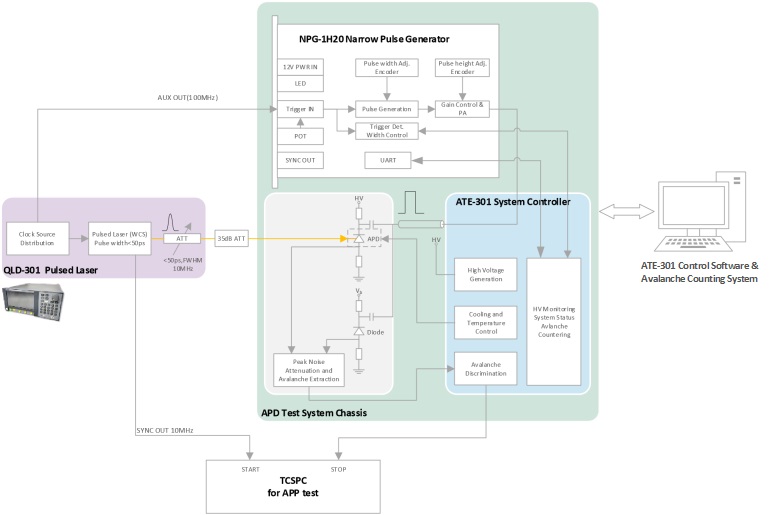
                                                                      Figure 1  System composition and principle-block diagram of the SPAD test platform


The QLD-301 picosecond pulsed laser includes:

● Signal generator module (Clock source distribution): It can receive an external reference clock or use an internal clock source to generate a synchronized laser pulse trigger clock and APD gated clock with adjustable relative delay. In general , the frequency of the APD gate control clock is an integer multiple of the laser trigger clock, and the system provides options of 2 times, 5 times, 10 times, 20 times, 50 times, and 100 times;

● Picosecond pulsed laser (Pulsed Laser): It can generate laser pulses synchronized with the trigger clock at the same frequency, the pulse width is less than 50ps, and the extinction ratio is greater than 40dB. In addition, the laser synchronization clock generated by it is used as the input signal of the counting module;

● Optical power monitoring and attenuation control module (ATT): control the attenuation of the laser pulse to attenuate it to the level of single photon and ensure the stability of the pulse power through high-sensitivity optical power monitoring.


NPG-1H20 gate control generation module mainly includes:

● Trigger input and monitoring unit, the trigger frequency covers 0.1~100MHz, compatible with any level trigger input;

● The gate control amplitude is adjustable, the adjustment range covers 4~6.4V, better than 100mV/step, the encoder adjustment;

● The gate width is adjustable, the adjustment range covers 0.5~2ns, 10ps/step, and encoder adjustment.


ATE-301 test main control module mainly includes:

● SPAD-related modules: including High Voltage Generation, Cooling and Temperature Control and other modules; the system is based on the gated quenching method so that the SPAD works in the gated mode, and in this mode, the detection efficiency, normalized dark count rate and post-pulse probability of the SPAD are tested;

● Dual channel counter module (dual channel counter): used to count the avalanche count value and can be upgraded to a coincidence counting module later, and automatically measure the post-pulse probability by synchronizing the clock with the laser to automatically find the peak and count the coincidence function.

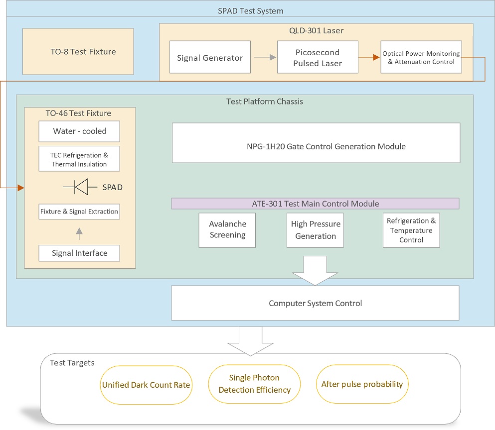
                                                                                    Figure 2  Schematic Diagram of the Composition of the Scheme


TO-46 test fixture mainly has:

● Water-cooled TEC refrigeration and thermal insulation structure: using industrial grade three-stage refrigeration sheet, combined with water-cooling heat dissipation technology, temperature control of ≤-60 °C can be achieved at room temperature of 20 °C, meeting the low temperature requirements of SPAD; Minimize heat radiation and heat convection.

● SPAD fixture and analog front end: It adopts unique pure copper heat conduction fixture and high-speed balanced differential technology to support SPAD in TO-46 package (maximum outer diameter 6mm, package structure is shown in Appendix 1), and the structure is easy to replace; High suppression of spike noise, which can effectively extract the avalanche signal of SPAD; 

● Signal interface: including optical pigtail exit, RF coaxial and DB9 interface, which are used to transmit single-photon signal, gated input signal, avalanche output signal and high voltage and temperature control interface of the system host respectively.


Performance

The specific performance index parameters are shown in the table below.


Parameter   Specification Remark
Laser QLD-301-1550
Laser Repetition Rate  1MHz~1.25GHz For SPAD test systems, the recommended laser pulse frequency range is 1MHz~100MHz , internal trigger 
Minimum Pulse Width  < 50ps, FWHM   
Time Jitter  < 20ps,RMS  Measured Relative to SYNC OUT 
Pulse Extinction Ratio  >40dB  
Center Wavelength  1550nm  
Internal Trigger Delay Range  0~1000ns SPAD test system uses internal triggering to generate an AUX OUT synchronous clock for Gated trigger clock for SPAD 
Delay Adjustment Accuracy  10ps  
Optical Power Monitoring Sensitivity  <-75dBm The internal PD sensitivity is better than -75dBm , and the external 35dB solid attenuation can support the minimum power detection range of -110dBm , which meets the optical power detection requirements of μ = 0.1 at 1MHz . 
Internally Adjustable Attenuation Range  0~40dB  
Auxiliary Clock Output Frequency  1MHz~1.25GHz As the SPAD gate trigger clock frequency, it can be set to an integer multiple of the laser pulse repetition frequency 
Gated Generation Module NPG-1H20
Gated External Trigger Frequency  Covers 0.1~100MHz  
Gate Width  Covering 0.5~2ns , 10ps/step Encoder adjustment 
Gate Amplitude  Covers 4~6.4V , better than
100mV/step
Encoder adjustment 
Pulse Polarity  positive pulse   
Rise Time  <120ps 20%~80%
Fall Time  <150ps 20%~80%
Test the Main Control Module ATE-301-SYS
High Pressure Range  50~90V adjustable   
High Voltage Regulation Resolution  0.01V  
Limit Cooling Temperature  -60 ℃  In the laboratory room temperature 20 ℃ environment, and maintain good ventilation 
Temperature Control Accuracy  ± 0.1 ℃   
Cooling Time  <8min  
TCSPC post-pulse test (currently using TCSPC for post-pulse test, subsequent functions can be upgraded and embedded in ATE-301-SYS) 


System Connection Block Diagram 

The figure below is the system connection block diagram, in which the ATE-301-SYS, NPG-1S20 and TO-46 test fixtures are all located on the test platform chassis, which can reduce the system size and facilitate operation.


                                                                                       ATE-301 TO-46 SPAD test system connection block diagram 


                                                     Applicable APD Package TO-46 Example Diagram


Appendix A. Calibration method for the average number of photons per pulse of laser pulses 

Before the performance test of the SPAD, it is necessary to accurately calibrate the average number of photons per pulse of the laser. The calibration process has the following methods:


1. Indirect power calibration method: Calculate the required output power according to the optical pulse repetition frequency and the average number of photons per pulse[2] , and then calculate the required external attenuation value according to the output power of the QLD-301 (displayed value or measured value), hand-held optical power The attenuation value of the external attenuator is calibrated so that the final output power reaches a predetermined value. The main problem of this method is that it requires additional calibration of the value of the external attenuator, which is complicated in operation.


2. Direct power calibration method: This method uses a high-precision instrument-type optical power meter, such as Keysight 81634B, whose nominal measurement accuracy can reach -110dBm, but the actual measurement accuracy is about -100dBm. If the average number of photons per pulse is required to be 0.1, this method only It can be used to calibrate optical pulses with repetition rate above 10MHz. The main problem of this method is its limited scope of application and high cost.


3. Single-photon counting direct calibration method: This method uses a single-photon detector whose detection efficiency has been calibrated for direct single-photon counting. Because the detection efficiency is known, the average number of photons per pulse can be directly calculated through the counting rate and the optical pulse frequency[3] . The method has fast calibration speed, good repeatability, a wide application range, simple and efficient.


The characteristics of the above three schemes are compared in the following table:


Calibration Method Complexity Cost Measurement Accuracy
Indirect Power Calibration Method High Low Low
Direct Power Calibration Method Low High Middle
Single Photon Counting Direct Calibration Method Low Middle High


[1] If SPAD is in Geiger mode, this parameter usually needs to be given with a certain dead time parameter, but this system uses gated control mode, and its default dead time is the length of one pulse period, so the dead time is generally the minimum value here. If necessary, the setting of dead time can be increased by parameters.

[2] For example, the average power of the 1550nm optical pulse at 1MHz with μ=0.1 is -108.92dBm

[3] If the single-photon detection efficiency SPDE=10%, the count rate of the 1MHz optical pulse with μ=0.1 is 10KHz.


Related Product